

FRP Composite Camels
FRP Camels
With camels providing the stand-off distance between vessels and piers, the use of FRP composite materials for the camel structures takes advantage of the big benefits of FRP composite materials: corrosion resistance and design flexibility.
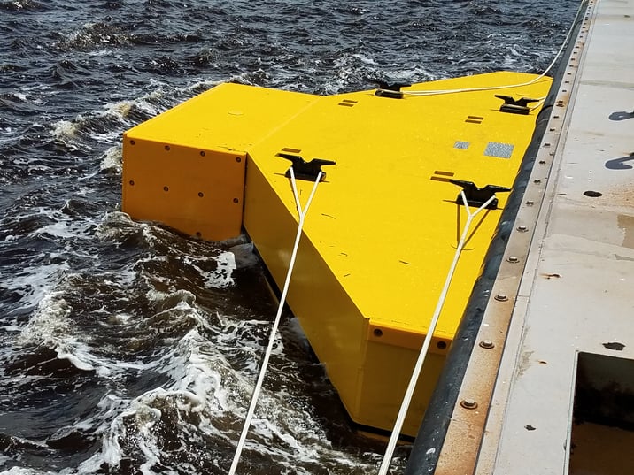
Camels are typically used in sets of two and float in different types of water for the entire useful life. For steel and wood camels that meant the owners had to remove the camels every two years for maintenance. This constant operational cost is a drain of tight fiscal budgets and the impetus for customers such as the US Navy, US Coast Guard, and commercial ports to implement FRP composite camels. The design life for the FRP composite camels is 25 years without maintenance.
COMPOSITE CAMELS ARE ROBUST AND COME IN A VARIETY OF SIZES
Camels are designed to handle a wide range of berthing loads from vessels. The size ensures that the pier piles are not overloaded during berthing. The top surface has a non-slip overlay for personnel safety. The natural buoyancy of the FRP panels allows for robust flotation of the structure.
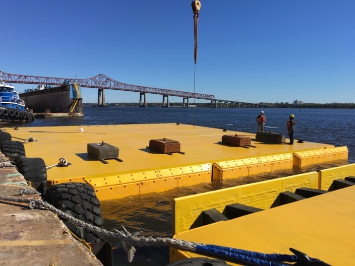
FRP CAMEL OFFERINGS INCLUDE:
- Ship-To-Shore Camels — Used in commercial ports, these basic camels can be supplied in any size.
- Floating Log Camels — These cylinders are used with small and medium vessels to spread the berthing loads across pier piles.
- Submarine Camels — Developed for the US Navy in 2009, these universal camels accommodate any class of submarine.
- Aircraft Carrier Camels — With the high strength of steel, these large camels handle high berthing loads.
CCG offers standard camels designs, with custom solutions available to address any ship loading and pier configuration. The Design & Build expertise of Creative Composites Group can provide the optimum solution.